
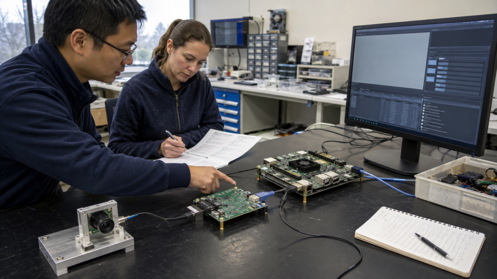
A camera module should not enter an OEM design only because it powers on, streams video and matches a nominal interface.
For UAV, UGV, Robotics, AMR and Autonomous Systems, the video module is the beginning of a machine-information path:
CAMERA → INTERFACE → COMPUTE → VIDEO PIPELINE → AI INPUT → PERCEPTION / DECISION
Every handoff can change what the system receives.
The purpose of a Video Input Readiness Review is not to certify the complete autonomy stack. It is to determine whether the input path is sufficiently defined, testable and reproducible for the OEM to continue evaluation.
The following seven questions form a compact pre-design-in review.
01 — What Task Must the Video Input Support?
“Good image quality” is not an acceptance criterion.
The same stream may serve remote operation, visual odometry, detection, tracking, inspection or recording. Each task values different information.
Motion blur that is tolerable to an operator may damage feature tracking. Compression that looks acceptable on a monitor may remove weak texture needed downstream.
Review focus
What task must the video input support?
In which operating environment?
What is the consequence if critical visual information is lost?
What evidence would demonstrate that the input remains useful?
Start with the task, intended environment and failure consequence. Then define what evidence would show that the input remains useful.
02 — Where Does the Accepted Configuration Begin and End?
A successful test result is meaningful only when the tested configuration can be identified and reproduced.
Record the complete evaluation configuration:
Camera module
Sensor and lens
Mechanical mounting
Power supply
Interface hardware
Firmware and driver
ISP profile
Output format
Encoder and transport
Compute platform
Relevant software versions
Configuration identity is not paperwork.
Without it, a successful sample cannot be reproduced and a later regression cannot be localized.
The OEM should also identify ownership at every boundary. A module supplier can support the video input and its integration, but the OEM retains responsibility for task thresholds, perception behavior and final system approval.
03 — Does Geometry Remain Valid?
Resolution alone does not define geometric equivalence.
The following variables can all change the relationship between pixels and the physical scene:
Lens
Sensor active area
Crop
Scaling
Rotation
Distortion correction
Mechanical alignment
ROS camera pipelines explicitly separate image data from calibration and projection information—a useful reminder that geometry travels with the image.
For stereo, visual odometry, SLAM or measurement workflows, a module or lens change may require recalibration even when the connector and nominal resolution remain unchanged.
Design-in question: If the module, lens, mounting or image-processing path changes, does the existing calibration remain valid?
04 — Is Timing Defined from Exposure to AI Input?
A latency result is meaningful only when its endpoints and clock assumptions are clear.
Document:
Where timestamps are created
Which clock domain owns them
How frames are buffered
What happens during compute load
What happens during packet delay
What happens after stream loss or restart
The permitted skew and pairing policy for multiple sensors
ROS 2 synchronizers align messages by timestamps. GStreamer documents how live sources, clocks, buffers and sinks affect latency.
These tools demonstrate why timing is a system property. They do not provide a universal pass threshold. The acceptable limit must come from the OEM task.
Useful timing evidence may include:
Time to first frame
P50, P95 and P99 latency
Frame loss
Timestamp consistency
Synchronization error
Time to recovery
05 — Is the Imaging Policy Valid Across the Operating Envelope?
Low-light performance is not a single brightness score.
Longer exposure increases collected light but may also increase motion blur and reduce achievable frame rate. Higher gain can preserve a shorter exposure but introduces more noise.
ISP operations such as denoising, sharpening and tone mapping may improve visual appearance while changing the features used by downstream algorithms.
A credible evaluation matrix should combine:
Illumination
Dynamikumfang
Platform motion
Target motion
Vibration
Exposure ceiling
Gain behaviour
Task output
Platform-specific conditions
UGV
Dust, vegetation, shadows, wheel-induced vibration and night movement.
UAV
Angular motion, changing altitude, rapid lighting transitions and constrained video transport.
Robotics and AMR
Occlusion, human interaction, indoor–outdoor transitions and repeated exposure changes.
The relevant question is not simply whether the image looks better. It is whether the imaging policy preserves the information required by the task.
06 — What Happens When the Path Degrades?
A healthy bench stream is necessary—but incomplete evidence.
Deliberately introduce representative failure conditions:
Late packets
Dropped frames
Compute saturation
Cable or network interruption
Process restart
Power-cycle recovery
Then define the expected response.
Should the system wait, discard the frame, reconnect, declare the stream invalid or enter another degraded state?
The review should evaluate both observability and recovery:
Can the system detect that the video input is stale, delayed or incomplete—and can it return to an accepted state predictably?
A stream that recovers unpredictably can create greater engineering risk than one that fails clearly.
07 — What Change Forces Re-Evaluation?
Define change triggers before production.
A change may preserve electrical compatibility while altering the actual AI input.
Potential re-evaluation triggers include:
New sensor
New lens
Revised mechanical mounting
Modified ISP profile
Firmware update
Driver update
Encoder-setting change
Compute-platform change
New supplier
Production hardware revision
NIST’s AI RMF resources emphasize measurement, documented limits, monitoring and change management for AI systems and connected components.
Applied to the video-input layer, this means maintaining:
A versioned reference configuration
A representative input dataset
Recorded acceptance criteria
A documented evaluation decision
Clearly defined regression triggers
Possible review decisions
Approved for the defined operating envelope
Conditionally approved after a specified software, calibration or integration change
Rejected because an acceptance threshold is exceeded
Unresolved because the available evidence is insufficient
Uncertainty should remain visible rather than being converted into a marketing claim.
From Specification Matching to Evaluation Readiness
Specifications still matter—but only in relation to the system risk they create or control.
Interface, power, resolution, frame rate, latency, low-light behaviour and encoding become useful when they are connected to:
The target platform
The complete video path
The operating envelope
Task-specific acceptance evidence
Reproducible evaluation conditions
That is the practical meaning of AI-ready video input.
It is not a promise that a camera contains the complete intelligence. It is an engineering condition in which the data path into the OEM’s perception workflow is defined, testable and reproducible.
Preparing a Camera-to-AI Evaluation?
Thyraon focuses on AI-ready embedded video modules and video-integration support for UAV, UGV, Robotics, AMR and Autonomous Systems OEM projects.
OEM engineering teams can contact Thyraon to discuss:
Platform and operating conditions
Camera and interface boundaries
Video-pipeline integration risks
Evaluation configurations
Technical documentation required before module selection
Discuss your video-input requirements with Thyraon before design-in.