
Thermal input / multispectral evaluation
Select the thermal core by interface, lens and workflow.
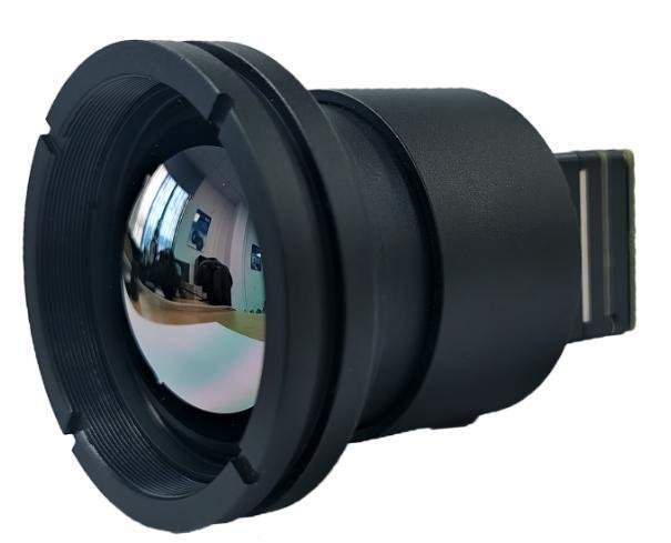
Four thermal series separate CVBS/UART and USB/UVC paths while keeping lens options and conditional distance metrics attached to the exact configuration.
System role
Thermal scene to detector and thermal video output to customer compute, display or multispectral workflow.
The category defines where a module may enter the customer architecture. Exact interfaces, ownership boundaries and validation requirements still change by model.
- 01 Thermal scene Evaluation path
- 02 Thermal detector and selected lens Evaluation path
- 03 CVBS or USB/UVC video output Evaluation path
- 04 Customer compute or display Customer-owned
- 05 Customer-owned multispectral or perception workflow Customer-owned
Four thermal series with separate video paths
Source-listed parameters support comparison. Final selection still requires the exact model, revision, interface and customer test conditions.
Choose the series by array, output path and lens family first. Distance figures remain attached to a selected lens and documented test assumptions.
CUSTOMER VERIFICATION REQUIRED
| Series | Array / pitch | Bildrate | Video / control | Lens options | Input | Strom | Envelope |
|---|---|---|---|---|---|---|---|
| CV256 | 256 × 192 / 12 µm | 50 Hz | CVBS (PAL) / UART | 4 or 9 mm | DC 4.5–18 V | ≤0.8 W | 21 × 21 × 29.8 mm / 23 g |
| CV640-TIF | 640 × 512 | 60 Hz | CVBS (PAL) / UART | 6.8 / 9 / 13 / 18 / 25 / 35 / 50 mm | DC 5–18 V | ≤0.8 W | 21 × 21 mm body; length and mass vary by lens |
| UV256 | 256 × 192 / 12 µm | 50 Hz | USB / UVC; USB control | 4 or 9 mm | USB 5 V | ≤0.8 W | 21 × 21 × 29.8 mm / 23 g |
| UV640-TIF | 640 × 512 | 60 Hz | USB / UVC; USB control | 6.8 / 9 / 13 / 18 / 25 / 35 / 50 mm | USB 5 V | ≤0.8 W | 21 × 21 mm body; length and mass vary by lens |
Documented 9 mm configuration reference
- CV640-TIF-9 field of view
- 46.2° × 37.7°
- CV640-TIF-9 distance table
- Detection 900 m / recognition 225 m / identification 113 m
- Operating range
- −20 to +60 °C listed for the reviewed series
- Detector band
- Uncooled VOx / 8–14 µm
- Detection, recognition and identification are different metrics. The listed 9 mm values are source reference values, not guaranteed customer-platform performance.
- Target size, thermal contrast, atmosphere, lens, installation, processing and acceptance method must be defined for customer evaluation.
What to confirm
Selection questions before a model enters evaluation.
- 01
Does the host require CVBS/UART or USB/UVC video and control?
- 02
Which lens and FOV fit the target geometry and mounting envelope?
- 03
What target, environment and test conditions define detection, recognition and identification evaluation?
Verification gates
A category match is not yet a platform match.
Each evaluation unit must remain tied to its exact model, revision, selected options, source status and customer acceptance criteria.
Electrical and interface
Connector, pinout, direction, voltage level, signaling, protocol, host, driver and firmware.
Mechanical and environmental
Envelope, mounting, optics, cabling, vibration, heat path, installation and operating conditions.
Workflow and acceptance
Video or data path, degraded-state behavior, measurements, thresholds and change triggers.
Next engineering decision
Review Thermal Imaging Modules against your platform constraints.
Share the platform context and the engineering constraints already known. Thyraon will use them to frame the next evaluation step.