
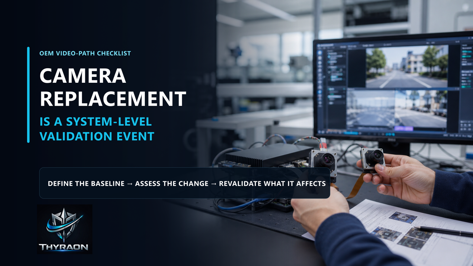
Short answer: replacing an embedded camera module should trigger an impact review across the complete video-input path. Matching resolution, frame rate or interface name does not guarantee matching electrical behaviour, format, latency, recovery or AI-input consistency. OEM teams should define the accepted baseline, identify what changed and repeat the tests affected by that change.
Why a component replacement can become a system change
A camera module sits at the beginning of a larger path:
CAMERA → INTERFACE → COMPUTE → VIDEO PIPELINE → AI INPUT
The downstream system does not consume a sensor data-sheet headline. It consumes frames delivered through a specific electrical, software and timing configuration.
Two modules may advertise the same resolution and nominal frame rate while differing in power-up sequence, pixel format, colour processing, timestamp behaviour, buffering, exposure control, lens geometry, recovery time or host dependency. Any of these differences can affect what reaches the AI pipeline.
This does not make camera replacement impossible, and it does not mean every test must be repeated. It means the replacement must be handled as a controlled configuration change.
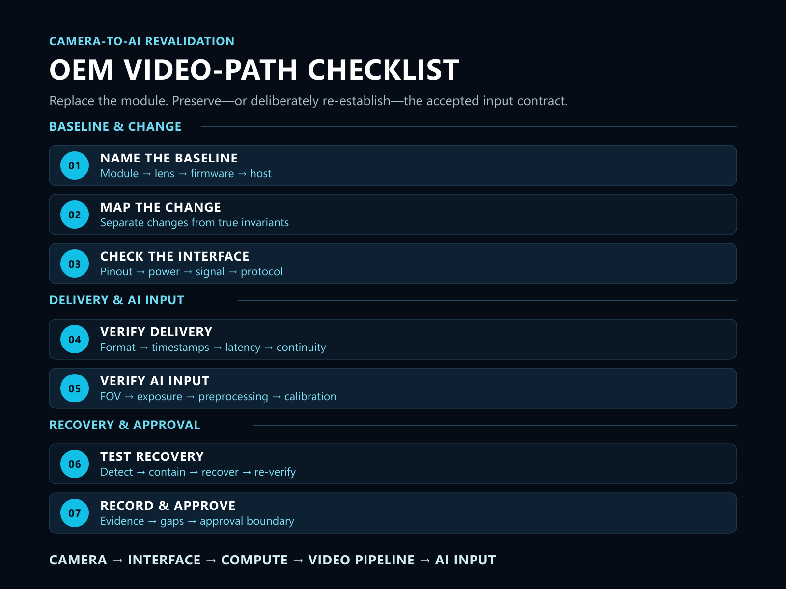
Step 1: Name the accepted baseline
Revalidation starts by identifying what was actually tested and accepted.
The baseline may include:
- exact module, sensor and hardware revision;
- lens, focal length and field of view;
- firmware and default ISP configuration;
- interface board, cable and pinout;
- power source and power-up sequence;
- host compute platform, operating-system image and driver;
- output format, dimensions and frame rate;
- mounting position and calibration association;
- relevant environmental and compute-load conditions.
A part number alone is rarely enough. If the accepted configuration cannot be named, it cannot be reproduced or compared reliably.
Step 2: Identify the change and its downstream reach
The impact review should distinguish what changed from what remained invariant.
A lens change may affect field of view, distortion, target pixel size and calibration. A firmware or ISP change may alter exposure behaviour, colour processing, defaults or output timing. A cable or interface-board change may affect signal integrity, power margin or recovery. A host-image or driver change may alter negotiation, buffering and control behaviour.
The useful question is not whether the change appears small. It is which acceptance criteria depend on it.
Step 3: Revalidate the electrical and interface contract
A connector that fits is only the first condition.
Confirm, where applicable:
- physical connector and pinout;
- signal direction and electrical levels;
- power input, inrush and reset behaviour;
- signalling standard and protocol;
- supported operating mode;
- host driver, SDK or middleware dependency;
- firmware and operating-system version;
- disconnect and reconnect behaviour.
Compatibility is a versioned contract between both sides of the interface—not a connector shape.
Step 4: Revalidate format, timing and frame delivery
The host should confirm what was actually negotiated after initialisation and after recovery:
- width and height;
- pixel format and colour interpretation;
- nominal and observed frame rate;
- source and host timestamps;
- frame sequence progression;
- buffering and end-to-end latency;
- dropped, duplicated, delayed or out-of-order frames;
- behaviour under representative compute load.
Average FPS alone can conceal long gaps or tail-latency events that matter to an AI or operator workflow.
Linux V4L2 documentation illustrates that formats and streaming methods are negotiated and that available controls can vary by device and configuration. A successful open or stream-start operation proves that data is flowing; it does not prove that the original video contract has been reproduced.
Step 5: Revalidate the image as an AI input
The image should be assessed inside the intended downstream workflow, not only on a display.
Depending on the application and approved test boundary, review:
- field of view and scene coverage;
- exposure and motion behaviour;
- low-light, backlight or thermal conditions where relevant;
- vibration and mounting effects;
- preprocessing, resize, crop and colour conversion;
- calibration and geometry assumptions;
- input distribution seen by the customer model;
- degraded-state behaviour when image quality becomes uncertain.
Thyraon should not claim that a module guarantees customer-model performance. The OEM team owns validation against its platform, dataset, model and operating conditions.
Step 6: Revalidate interruption and recovery
A replacement module may stream normally but recover differently after a fault.
Controlled evaluation may include interface disconnect, module power interruption, host restart, capture-process restart or pipeline rebuild. The exact tests depend on the customer architecture and approved safety boundary.
For each scenario, define:
- how degradation is detected;
- how stale or invalid frames are contained;
- which component owns recovery;
- retry count, timeout and escalation condition;
- which fields are re-verified after recovery;
- what evidence is recorded.
The sequence is:
DETECT → CONTAIN → RECOVER → RE-VERIFY → RECORD
A restored stream is not yet a restored AI input. Device identity, format, timestamps, frame freshness, exposure settling, calibration association and latency may still need confirmation.
Step 7: Record evidence and approve the new baseline
The final result should connect the change, the tests and the approved configuration.
Record at least:
- previous and candidate configuration identities;
- reason for replacement or second-source qualification;
- changed and unchanged fields;
- affected acceptance criteria;
- test environment and platform conditions;
- results, exceptions and unresolved gaps;
- final approval, rejection or customer-verification-required status.
This turns “the new camera worked on the bench” into evidence that an OEM team can review and reproduce.
Module, host and customer-system responsibilities
Responsibility should remain explicit:
- Video module: exposes its verified output and available status or reinitialisation behaviour.
- Interface and host pipeline: negotiates, transports, timestamps, validates freshness and reports errors.
- Customer perception or control system: decides whether to continue, pause, fall back or enter a defined safe state.
Thyraon does not replace the customer’s perception, autonomy, decision or final validation architecture.
From replacement candidate to OEM evaluation
The strongest acceptance statement is not:
The replacement camera produces a clear image.
It is:
Under a named configuration and defined operating conditions, the replacement preserved or re-established the required electrical, format, timing, recovery and AI-input contract, with documented evidence and identified customer-verification boundaries.
Thyraon provides AI-ready embedded video modules and video integration support for FPV drone OEM projects. When a team is qualifying a replacement module or second source, the practical next step is to map the current baseline and agree the affected video-path acceptance criteria before testing.