
Video transport / OSD workflow
Evaluate the air unit inside the complete video-link path.
Compare Yunfeng 2K and 4K configurations by video mode, RF output, power, OSD workflow and documented integration conditions.
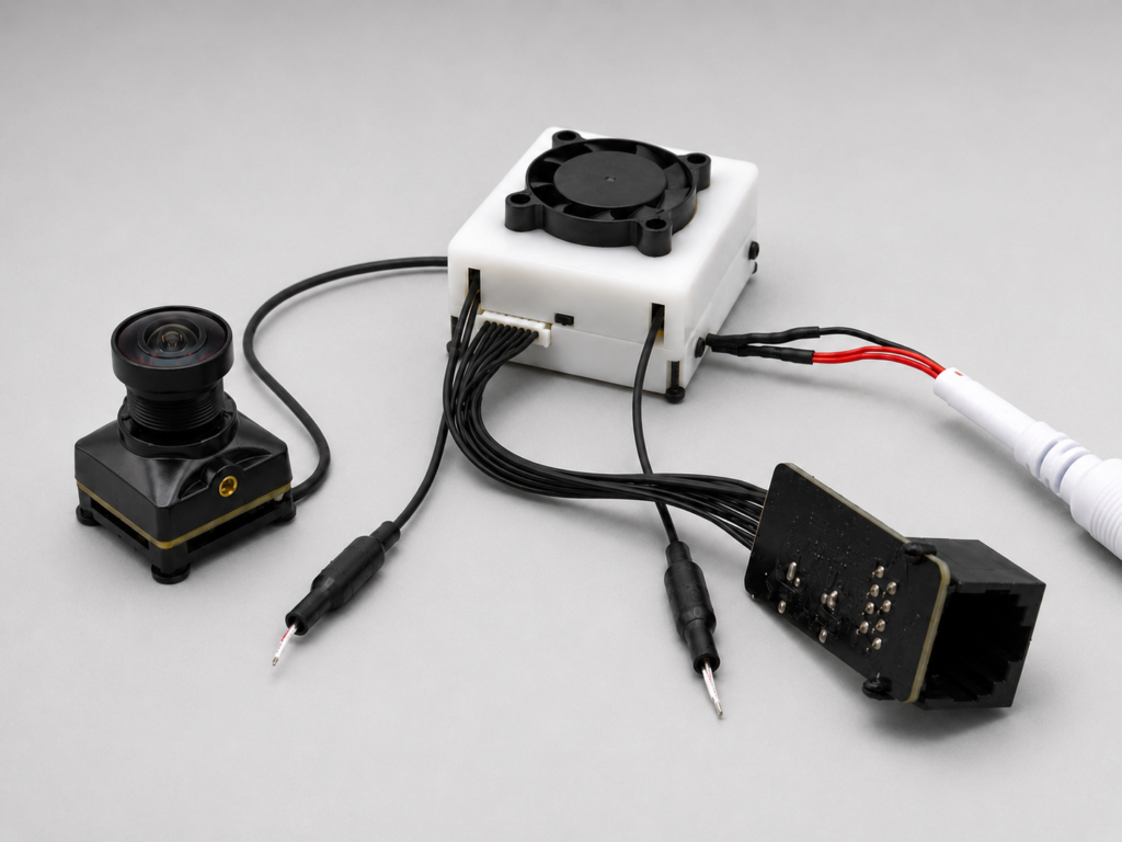
System role
Camera to encoding and transport to receiver, GCS, display or downstream compute.
The category defines where a module may enter the customer architecture. Exact interfaces, ownership boundaries and validation requirements still change by model.
- 01 Camera input Evaluation path
- 02 Encoding and air-side transport Evaluation path
- 03 RF link under documented conditions Evaluation path
- 04 Receiver / GCS / display Evaluation path
- 05 Customer platform workflow Customer-owned
Four documented Yunfeng configurations
Source-listed parameters support comparison. Final selection still requires the exact model, revision, interface and customer test conditions.
The 2K and 4K variants are separated by exact model, RF output and power configuration. Range remains a conditional test metric, not a universal field guarantee.
CUSTOMER VERIFICATION REQUIRED
| Model | Video modes | FOV | RF output | Power | Input | Mounting | OSD |
|---|---|---|---|---|---|---|---|
| THY-YF-AU-4K-V1 | 4K30 / 2.5K60 / 1080p90 / 720p120 | 160° | 20 dBm | 10 W | DC 5–30 V (2–6S) | 30.5 × 30.5 mm | MSPOSD / MAVFWD |
| THY-YF-AU-4K-V2 | 4K30 / 2.5K60 / 1080p90 / 720p120 | 160° | 29 dBm | 15 W | DC 5–30 V (2–6S) | 30.5 × 30.5 mm | MSPOSD / MAVFWD |
| THY-YF-AU-2K-V1 | 2816×1584p60 / 2.5K60 / 1080p90 / 720p120 | 140° | 20 dBm | 10 W | DC 5–30 V (2–6S) | 30.5 × 30.5 mm | MSPOSD / MAVFWD |
| THY-YF-AU-2K-V2 | 2816×1584p60 / 2.5K60 / 1080p90 / 720p120 | 140° | 29 dBm | 15 W | DC 5–30 V (2–6S) | 30.5 × 30.5 mm | MSPOSD / MAVFWD |
Shared source-listed functions
- RF band
- 5.8 GHz
- Lens / antenna
- 19 × 19 mm M12 lens / IPEX1 antenna connector
- Media
- TF recording, microphone and audio listed as supported
- Control
- Four PWM ports listed
- The source lists link ranges for named system configurations, but antenna, receiver, RF environment, installation and terminology require confirmation before any range value is used publicly.
- OSD, system compatibility, video mode and thermal behavior must be validated in the complete customer link path.
What to confirm
Selection questions before a model enters evaluation.
- 01
Which resolution, frame-rate, OSD and receiver workflow must the video link support?
- 02
What RF environment, antennas, installation and test conditions apply to range evaluation?
- 03
Which power, thermal and mechanical constraints apply to the air-side assembly?
Verification gates
A category match is not yet a platform match.
Each evaluation unit must remain tied to its exact model, revision, selected options, source status and customer acceptance criteria.
Electrical and interface
Connector, pinout, direction, voltage level, signaling, protocol, host, driver and firmware.
Mechanical and environmental
Envelope, mounting, optics, cabling, vibration, heat path, installation and operating conditions.
Workflow and acceptance
Video or data path, degraded-state behavior, measurements, thresholds and change triggers.
Next engineering decision
Review Digital Air Units against your platform constraints.
Share the platform context and the engineering constraints already known. Thyraon will use them to frame the next evaluation step.