
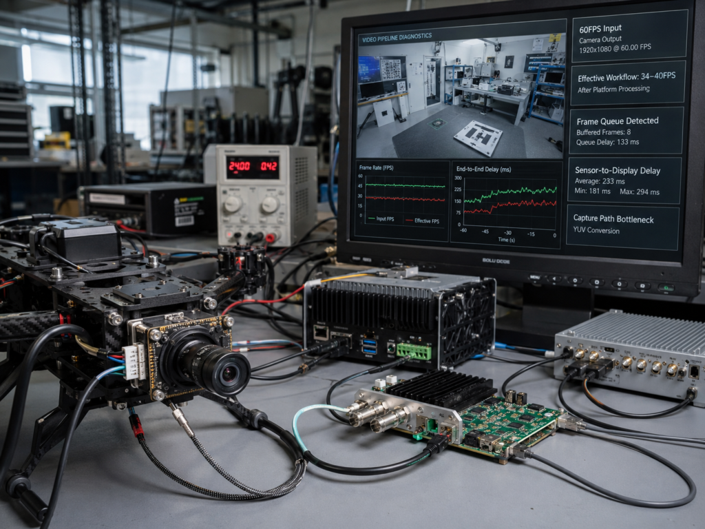
Short Answer: Why Camera FPS Is Not the Same as Workflow FPS
A 60FPS camera input does not guarantee a 60FPS video workflow because frame rate can degrade after the camera output.
The capture path, YUV handling, memory bandwidth, processing load, encoding, display scheduling, and AI inference workload can all reduce effective frame throughput and create accumulated latency.
For FPV drone teams, video performance should be evaluated from sensor output to compute board, and from video ingest to display, not only from the camera datasheet.
Why Camera Output Is Only the Beginning
In embedded vision and FPV drone video integration, camera specifications are often treated as if they describe the final system behavior.
They do not.
A camera can output high-resolution, high-frame-rate video correctly, while the platform still fails to ingest, process, transmit, or display those frames at the same rate.
This is where many video systems fail quietly.
The image appears.
The video stream exists.
The camera is not broken.
But the usable workflow becomes slower, less stable, and less predictable after integration.
That difference matters for FPV drone video integration projects.
The real engineering question is not only:
What can the camera output?
Daha iyi soru şu:
What does the full video workflow deliver after the signal enters the platform?
Key Definitions
Video Ingest
Video ingest is the process of receiving video frames from a camera or input source into the processing platform.
It is where the video signal first enters the board, driver, API, memory, or application layer.
Capture Path
The capture path is the hardware, driver, API, memory, and software path that moves frames from input to application.
A weak capture path can reduce effective frame rate even when the camera output is correct.
Frame Accumulation
Frame accumulation happens when frames arrive faster than the system can process or display them.
The video still appears, but the displayed frames may represent delayed information.
Effective Frame Rate
Effective frame rate is the frame rate actually delivered by the system after capture, processing, and display.
It is not the same as the camera output rate.
Latency Drift
Latency drift is a gradual increase or instability in delay during operation.
It can be caused by queue buildup, compute load, thermal load, memory pressure, background tasks, or processing bottlenecks.
Video Pipeline
A video pipeline is the full chain from sensor output to video ingest, processing, encoding, transmission, display, operator review, or AI inference.
Recent Engineering Signal: RK3588 Video Capture
A recent OpenCV forum discussion reported an RK3588 video capture issue involving HDMI YUV input.
The input signal was 4096×2160 at 60FPS.
The expected behavior was stable high-frame-rate video capture.
The observed behavior was different: the capture path delivered only around 30–40FPS, creating frame accumulation latency.
This signal matters because it shows that video latency can emerge after camera output, inside the capture and processing path.
The issue is not simply whether a camera can output video.
The issue is whether the board, driver, capture method, format handling, memory path, and processing workflow can sustain the required throughput.
When the capture path falls behind, the system may not immediately fail.
It may accumulate delay.
That delay can be more damaging than a visible failure because it gives the engineering team a false sense of system readiness.
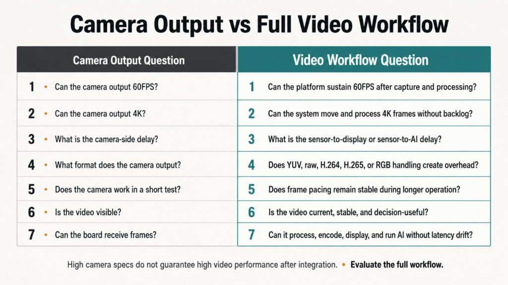
Camera Output vs Full Video Workflow
| Evaluation Area | Camera Output Question | Video Workflow Question |
|---|---|---|
| Frame rate | Can the camera output 60FPS? | Can the platform sustain 60FPS after capture and processing? |
| Çözünürlük | Can the camera output 4K? | Can the system move and process 4K frames without backlog? |
| Gecikme | What is the camera-side delay? | What is the sensor-to-display or sensor-to-AI delay? |
| Format | What format does the camera output? | Does YUV, raw, H.264, H.265, or RGB handling create overhead? |
| Compute load | Usually not measured at camera level | Does AI inference compete with video handling? |
| İstikrar | Does the camera work in a short test? | Does frame pacing remain stable during longer operation? |
Where Video Throughput Drops After Camera Output
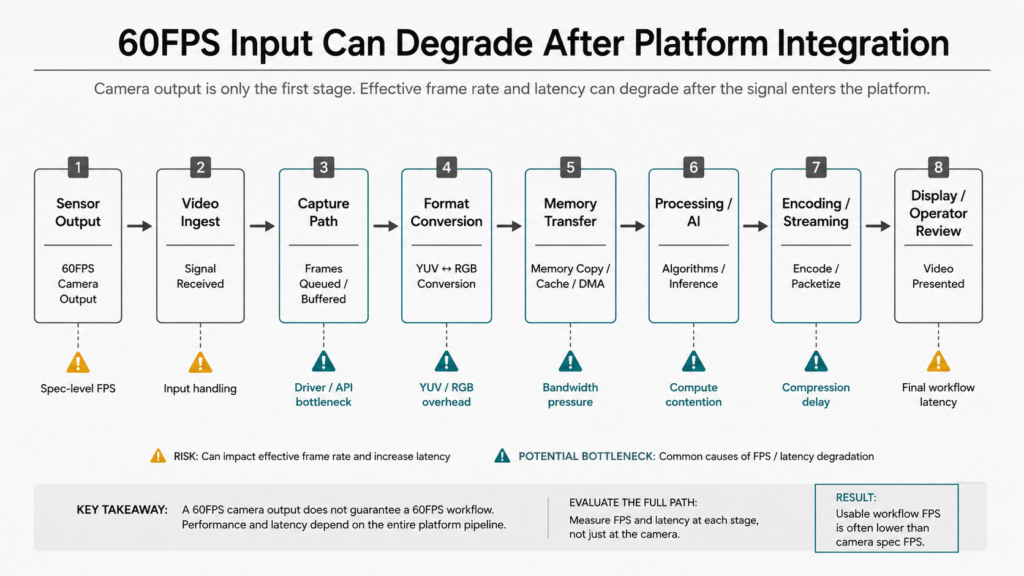
Camera output is only the first stage.
After output, the signal may pass through several stages:
- video ingest
- capture interface
- frame queue
- YUV or raw format handling
- color-space conversion
- memory transfer
- CPU, GPU, or NPU workload
- hardware encoding
- streaming
- receiver-side handling
- display output
- operator review
- edge-AI inference
Each stage can change the final behavior of the system.
A 60FPS input may become a lower effective frame rate if the capture path cannot keep up.
High-resolution video may increase memory bandwidth pressure.
YUV handling may create additional processing overhead.
Frame queues may build up when processing speed falls behind input speed.
Display output may look smooth during a short test, while latency accumulates over longer operation.
For engineering teams, this creates a dangerous false positive.
The system appears to work, but the video workflow is not actually stable.
Common Failure Modes in Embedded Vision Pipelines
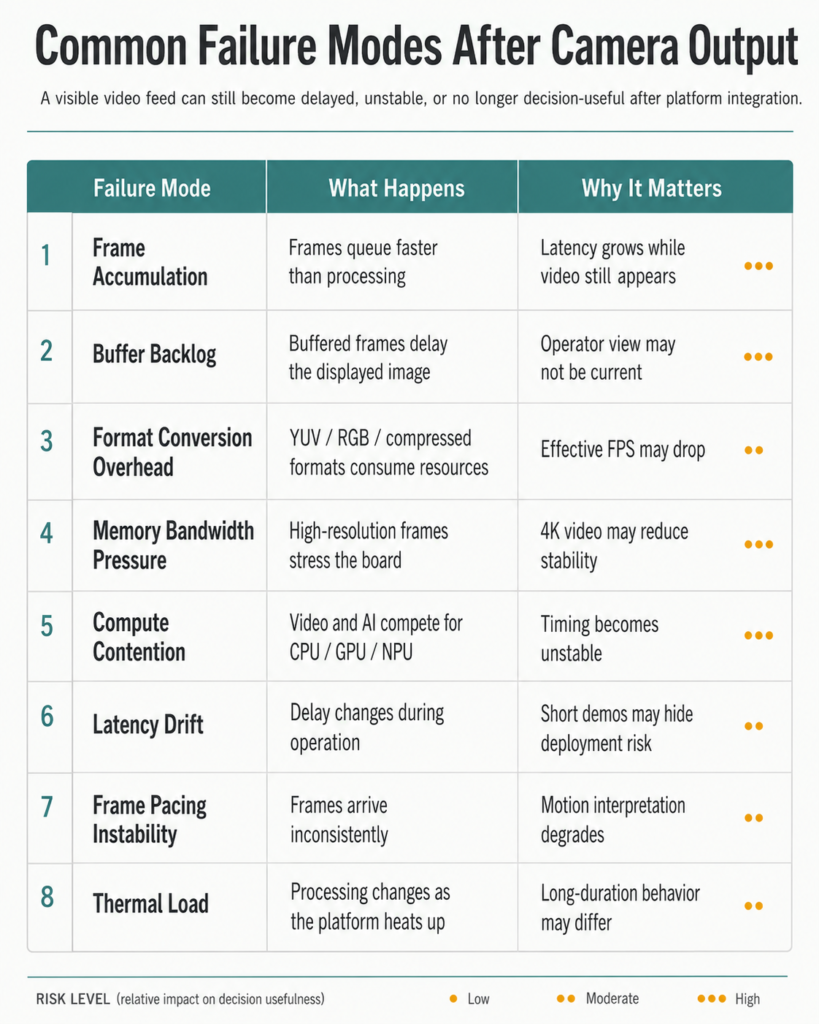
| Failure Mode | What Happens | Why It Matters |
|---|---|---|
| Frame accumulation | Frames queue faster than they are processed | Latency grows even when video still appears |
| Buffer backlog | Buffered frames delay the displayed image | Operator view may no longer be current |
| Format conversion overhead | YUV, raw, RGB, or compressed formats consume processing resources | Effective frame rate may drop |
| Memory bandwidth pressure | High-resolution frames stress system bandwidth | 4K video may reduce stability |
| Compute contention | Video and AI workloads compete for CPU, GPU, NPU, memory, or bus resources | AI inference may degrade video timing |
| Latency drift | Delay changes during operation | Short demos may hide real deployment issues |
| Frame pacing instability | Frames are delivered inconsistently | Motion interpretation and operator confidence can degrade |
| Thermal load | Processing performance changes as the platform heats up | Long-duration tests may behave differently from short demos |
Why This Matters for FPV drone, and Edge-AI Vision
FPV drone video is not used only for recording.
It often supports FPV pilot viewing, recording or optional onboard video processing.
In those workflows, latency and frame stability are not cosmetic issues.
They affect whether visual information arrives in time to support a decision.
For FPV drone platforms, unstable video throughput can affect operator confidence, motion interpretation, target review, and timing-sensitive control.
In all of these cases, the video is not judged at the sensor output.
It is judged after the signal survives the platform.
What Engineering Teams Should Test Before Camera Selection
Camera selection should not stop at resolution and frame rate.
For FPV drone video integration projects, teams should also evaluate:
| Test Area | Engineering Question |
|---|---|
| Effective frame rate | Does the platform actually deliver the expected FPS after capture and processing? |
| Frame pacing | Are frames delivered consistently, or does timing fluctuate? |
| Buffer behavior | Does the system accumulate frames during operation? |
| Format handling | Does YUV, raw, H.264, H.265, or RGB conversion add overhead? |
| Memory bandwidth | Can the board move high-resolution frames without bottlenecks? |
| Compute load | Does AI inference compete with video ingest or display? |
| Sensor-to-display latency | How long does it take for a frame to reach the screen? |
| Sensor-to-AI latency | How long does it take for a frame to reach the inference pipeline? |
| Long-duration stability | Does latency remain stable after extended operation? |
| Thermal behavior | Does performance change as the board or enclosure heats up? |
These questions are more useful than asking for a low-latency number in isolation.
A low-latency camera does not guarantee a low-latency system.
A high-frame-rate input does not guarantee a high-frame-rate workflow.
A clear image does not guarantee a usable visual system.
What This Means for FPV drone Video Integration
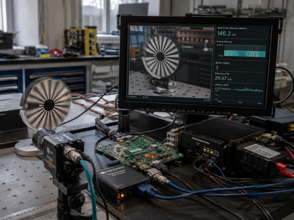
For Thyraon, this type of engineering signal reinforces a clear evaluation principle:
FPV drone video performance should be reviewed after camera output, inside the actual platform workflow.
For FPV drone video integration projects, the evaluation should include video ingest behavior, capture-path stability, frame throughput, format handling, latency drift, image usability, and compute-board fit.
The goal is not only to select a camera that can output video.
The goal is to build a visual workflow that remains current, stable, and decision-useful after integration.
FAQ: Video Pipeline Latency and Frame Throughput
Q1: Does a 60FPS camera always produce a 60FPS video workflow?
No. A camera may output 60FPS, but the platform may process, display, or transmit fewer frames if the capture path, memory bandwidth, format handling, or compute workload cannot sustain the input rate.
Q2: What is frame accumulation latency?
Frame accumulation latency happens when frames enter the system faster than they are processed or displayed.
The video still appears, but the displayed frames may represent delayed information.
Q3: Why can video latency happen after camera output?
Latency can happen during video ingest, driver handling, format conversion, memory transfer, encoding, display scheduling, network streaming, receiver-side processing, or AI inference.
Q4: Why is this important for FPV drone vision systems?
FPV drone pilots use video for real-time viewing; selected configurations may also record or process the image.
If frames accumulate or latency drifts, the visual workflow may become less useful even when the image is still visible.
Q5: What should engineers test besides camera resolution and FPS?
Engineers should test effective frame rate, frame pacing, buffer behavior, sensor-to-display latency, sensor-to-AI latency, format conversion load, memory bandwidth, compute workload, and long-duration stability under real operating conditions.
Q6: What is the difference between camera latency and video pipeline latency?
Camera latency refers to delay at or near the camera output.
Video pipeline latency includes the full path from sensor output to capture, processing, encoding, transmission, display, operator review, or AI inference.
Q7: Why can 4K video create latency even when the camera works correctly?
4K video increases the amount of data that must be moved, converted, processed, encoded, or displayed.
If the board, memory path, driver, or software pipeline cannot sustain that data rate, effective frame rate may drop and latency may accumulate.
Q8: Is a short demo enough to validate video latency?
No.
Short demos can hide buffer buildup, latency drift, thermal effects, and compute contention.
Engineering teams should test the video workflow under real resolution, frame rate, compute load, display path, and operating duration.
Q9: Why does video format matter?
Different video formats create different processing loads.
YUV, raw, RGB, H.264, H.265, and MJPEG workflows can behave differently depending on the board, driver, decoder, encoder, and application path.
Q10: What is the most important benchmark for embedded vision video performance?
The most important benchmark is stable video throughput after integration.
That means the system should preserve usable frame rate, timing stability, and decision-useful image output from sensor to screen, and from camera to compute.
Final Takeaway
A 60FPS input does not guarantee a 60FPS video workflow.
A camera can work correctly while the platform quietly loses frames, builds buffer backlog, or accumulates latency after video ingest.
For FPV drone projects, the real benchmark is not only whether the system can show video.
The real benchmark is whether the video remains current, stable, and decision-useful after integration.